VEML7700
Ambient light over I2C, at address 0x10. Power first, then the two data wires.
Before you start
Checkpoint 2 passed. USB unplugged while you seat jumpers.
Warning
Power from 3V3 only. After wiring, check for heat and, if you have a meter, about 3.3 V on the supply pin.
The power pin may be printed VIN, VCC or VDD. They all go to the 3V3 rail.
Many breakouts also have 3Vo (or 3V3). That is a 3.3 V output from the on-board regulator, not a power input. Leave it unconnected in this tutorial.
1. Power
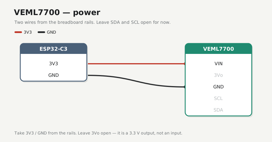
| From | To | |
|---|---|---|
+ rail (3V3) |
VEML7700 VIN / VCC / VDD | |
− rail (GND) |
VEML7700 GND | |
| — | 3Vo — leave open |
Leave SDA, SCL, and 3Vo open for now. Plug in USB and check that the module is cool. If you have a meter, expect about 3.3 V on VIN (optional):
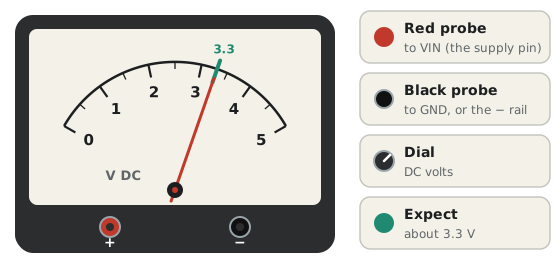
Unplug before adding the data wires.
2. I2C
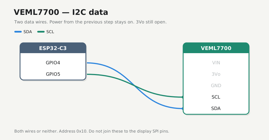
| ESP32-C3 | VEML7700 | |
|---|---|---|
| GPIO4 | SDA | |
| GPIO5 | SCL |
Both wires or neither. One alone will fail the later scan at 0x10.
Keep the buses apart
Do not join these to the display's SDA and SCL pins. Those are SPI.
If it fails
| Symptom | Fix |
|---|---|
| Module warm | Unplug. Check that VIN isn't on 5V, GND is on the − rail, and you didn't feed power into 3Vo |
| Meter doesn't read about 3.3 V | Confirm the ESP32 still feeds the + rail (checkpoint 2). If the sensor is on the other half of the board, bridge the mid-rail gaps (Breadboard) |
Flashing later shows no 0x10 |
Come back here. Check SDA and SCL aren't swapped, reseat both data jumpers, and shorten the wires |
Checkpoint 3
- VEML7700 VIN is on the 3V3 rail and GND on the GND rail; 3Vo has no wire
- GPIO4 to SDA and GPIO5 to SCL, both seated
- The module stays cool with USB plugged in (and about 3.3 V on VIN, if metered)
- No wires on the LED or display yet
Stop here until every box is ticked.
Next: LED