Validate
Walk the full pin map and confirm USB still works. Do not expect the display to light or the VEML7700 to report values here — that comes after you flash.
Before you start
Checkpoint 5 passed. Everything from the earlier steps stays wired.
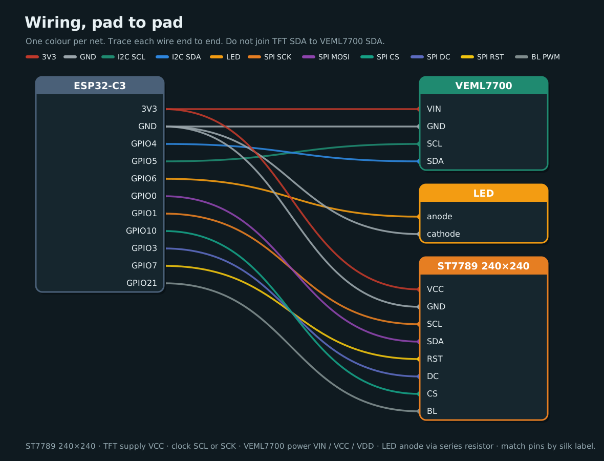
The full map
| ESP32-C3 | VEML7700 | LED | Display (ST7789) |
|---|---|---|---|
| 3V3 | VIN / VCC | VCC | |
| GND | GND | cathode | GND |
| GPIO4 | SDA | ||
| GPIO5 | SCL | ||
| GPIO6 | anode (via R) | ||
| GPIO0 | SDA (MOSI) | ||
| GPIO1 | SCL / SCK | ||
| GPIO10 | CS | ||
| GPIO3 | DC | ||
| GPIO7 | RST | ||
| GPIO21 | BL |
Rules
- 3V3 only for sensor and display logic.
- Do not join TFT SDA to VEML7700 SDA.
- Leave GPIO9 (BOOT) free for factory reset.
- Avoid GPIO18 / GPIO19 (USB D− / D+).
- Match pins by silk label, not by position on the header.
Check
| Check | What to look for | |
|---|---|---|
| Walk the map | Every row above has a jumper on the matching pin label | |
| Two separate buses | VEML7700 uses GPIO4 and 5. Display SDA/SCL use GPIO0 and 1 and never share a wire with them | |
| 3V3 only | No sensor or display pin is on 5V or VIN | |
| Cool | After a few seconds on USB, lightly touch the VEML7700, LED, and display. If anything is warm, unplug and recheck power and ground | |
| USB | Data cable in the board's USB port. Run the commands below |
lsusb | grep -iE '303a|Espressif|10c4|cp21|1a86|QinHeng|Silicon'
ls -l /dev/ttyACM0 /dev/ttyUSB0 2>/dev/null
Bus 001 Device 024: ID 303a:1001 Espressif USB JTAG/serial debug unit
crw-rw-rw- 1 root dialout 166, 0 Nov 11 23:23 /dev/ttyACM0
Expect either Espressif's built-in USB Serial/JTAG (303a) or a bridge such as CP210x (10c4) / QinHeng (1a86), and a port such as /dev/ttyACM0 or /dev/ttyUSB0. The panel may stay dark. I2C at 0x10, the LED, backlight, and the setup QR are checked on Flash.
If it fails
| Symptom | Likely fix |
|---|---|
| No serial port | Use a data cable (charge-only cables never show a port). USB group setup is in Flash |
| Something warm | Unplug. Start at 3V3 and GND, then the last wires you added |
| The map doesn't match | One jumper is on the wrong pin. Walk the table row by row |
| Display SDA tied to VEML7700 SDA | Separate the buses — TFT SDA is SPI MOSI on GPIO0 |
Checkpoint 6
- The full map matches the table above
- The I2C and SPI buses are not crossed
- The board shows up on USB (
lsusband a serial device) - Sensor, LED wiring, and display stay cool
Stop here until every box is ticked.
Next: Flash the ESP32