ESP32
Put the ESP32-C3 on the breadboard and feed the + and − rails from it. Later steps take power from those rails.
Before you start
Checkpoint 1 passed. USB unplugged while you seat jumpers.
Match pins by silk label, not by position. This tutorial uses an ESP32-C3 DevKit: one USB port for power and serial, BOOT on GPIO9. Some boards use a USB-to-UART chip; others (including the board used for these checks) use the chip's built-in USB Serial/JTAG.
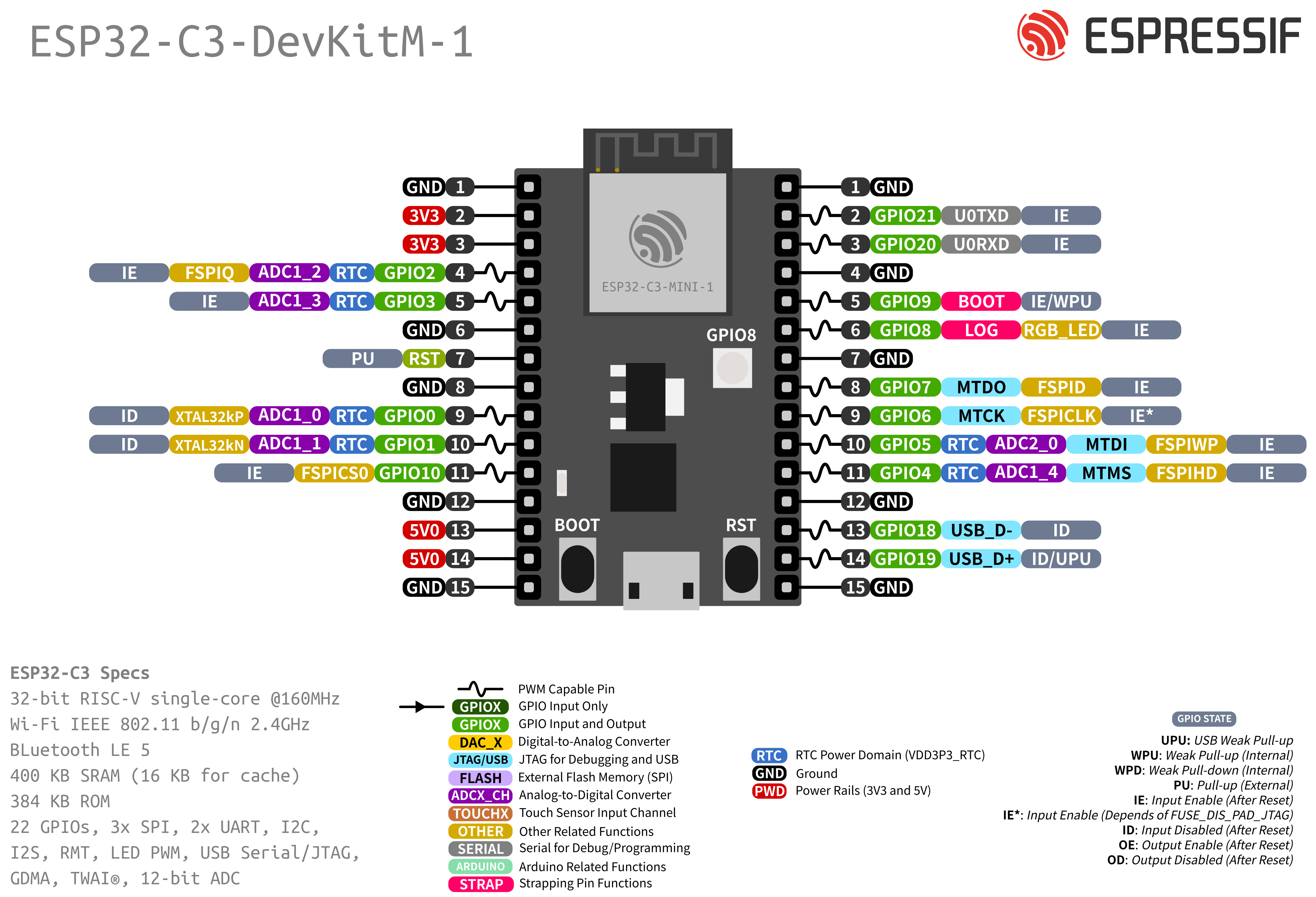
ESP32-C3-DevKitM-1 pin layout (Espressif) — use it to find 3V3, GND, BOOT (GPIO9), and GPIO numbers by silk. Your board's USB connector shape may differ.
Wires
| From ESP32 | To breadboard | |
|---|---|---|
| 3V3 | + rail |
|
| GND | − rail |
Bridge the rail halves
Many breadboards split each power rail in the middle — and each long edge has its own + / − pair. On the edge you use, seat a short jumper across the gap on both + and −, or modules on the far half get no 3V3/GND. See Breadboard.
Warning
Don't power the sensor or display from 5V or VIN.
Leave these pins free
| Pin | Why | |
|---|---|---|
| GPIO9 | The BOOT button, used for the factory reset | |
| GPIO18 / 19 | USB D− / D+ on the chip (Serial/JTAG) | |
| GPIO2 / 8 | Strapping pins (GPIO8 also drives the on-board RGB LED) |
Seat the board across the centre trench so each pin has its own breadboard row. Leave space beside it for the VEML7700, LED, and display.
Check
Plug a USB data cable into the board's USB port, then run:
lsusb | grep -iE '303a|Espressif|10c4|cp21|1a86|QinHeng|Silicon'
ls -l /dev/ttyACM0 /dev/ttyUSB0 2>/dev/null
Bus 001 Device 024: ID 303a:1001 Espressif USB JTAG/serial debug unit
crw-rw-rw- 1 root dialout 166, 0 Nov 11 23:23 /dev/ttyACM0
This capture is from a board that uses Espressif's built-in USB Serial/JTAG (303a). A DevKitM-1 with a CP210x bridge instead shows Silicon Labs (10c4) and may appear as /dev/ttyUSB0. Either is fine — you need a serial device for flash and logs.
Nothing on the board should get warm. Unplug before the next step.
If it fails
| Symptom | Fix |
|---|---|
No /dev/ttyACM* or /dev/ttyUSB* |
Try another data cable (charge-only cables never show a port) |
| Board warm | Unplug. 3V3 and GND may be swapped or shorted on the rail |
A meter on the + rail reads 5 V instead of about 3.3 V |
The rail is fed from the wrong pin. Move the wire to 3V3 |
| Only one half of the rail has ~3.3 V | Mid-rail gap. Bridge + and bridge − (Breadboard) |
Checkpoint 2
- Only 3V3 to
+and GND to−from the ESP32 (no sensor, LED, or display wires yet) - Rail gaps bridged, if your board has them
- The board shows up in
lsusband as a serial device - The board stays cool
Stop here until every box is ticked.
Pin layout: Espressif ESP32-C3-DevKitM-1 documentation.
Next: VEML7700