Breadboard
Nothing is wired yet. The plastic board already has metal clips under the holes — those clips decide what is connected. Learn that map before you seat any jumpers.
Before you start
Parts from the overview on the desk. Breadboard empty. No jumpers seated yet.
1. Look at your board
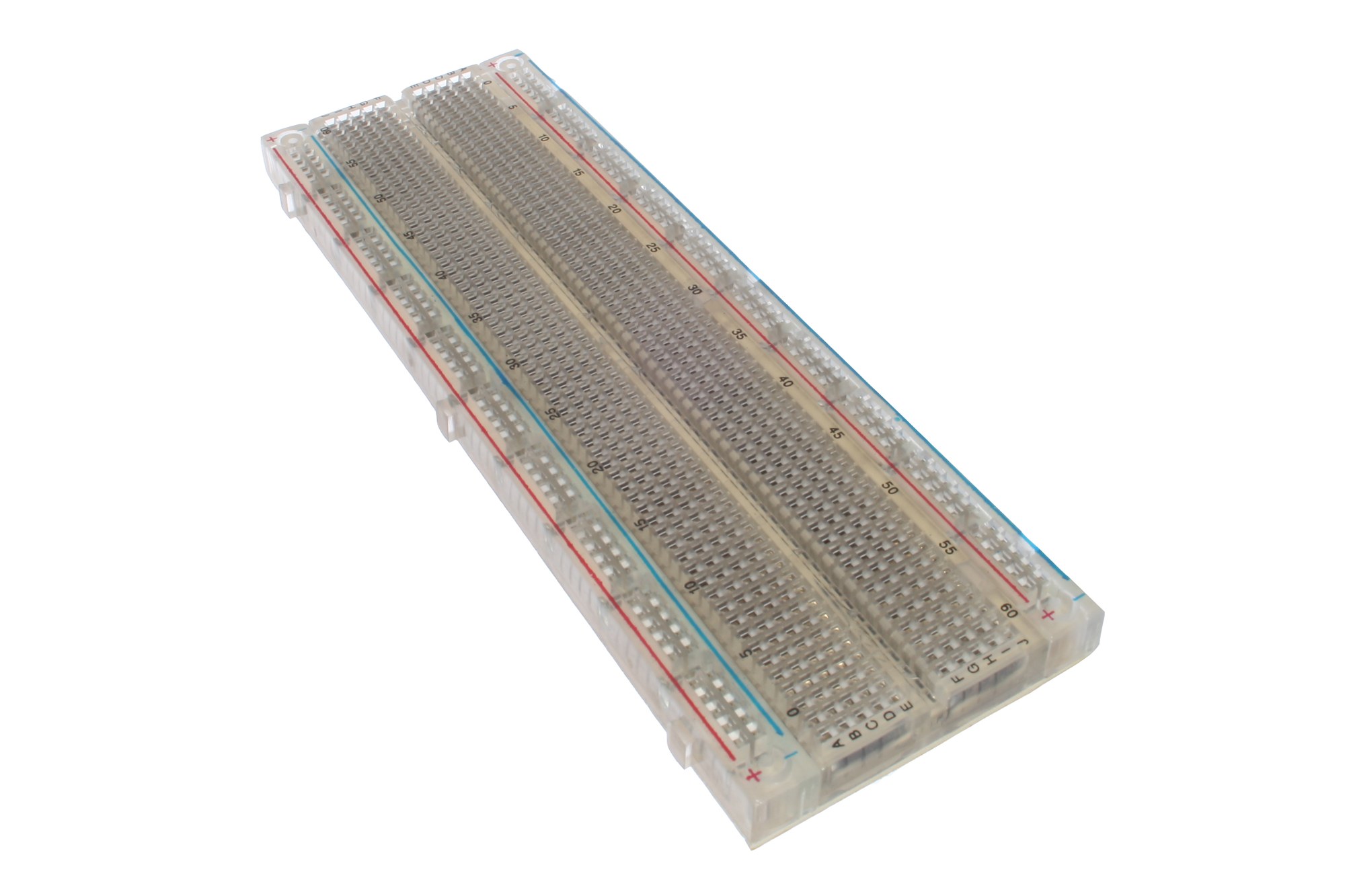
A typical full-size board. Yours may be half-size (400 holes) or full-size (830). The rules below are the same.
Find these three things on yours:
| What | Where |
|---|---|
| Centre trench | The groove down the middle |
| Letter columns | a–e on one side of the trench, f–j on the other |
| Power rails | The long + (often red) and − (often blue) columns along the edge |
2. What's already connected
Pull the sticky backing off a spare board once in your life and the clips look like this. You don't need to strip yours — the photo is enough.
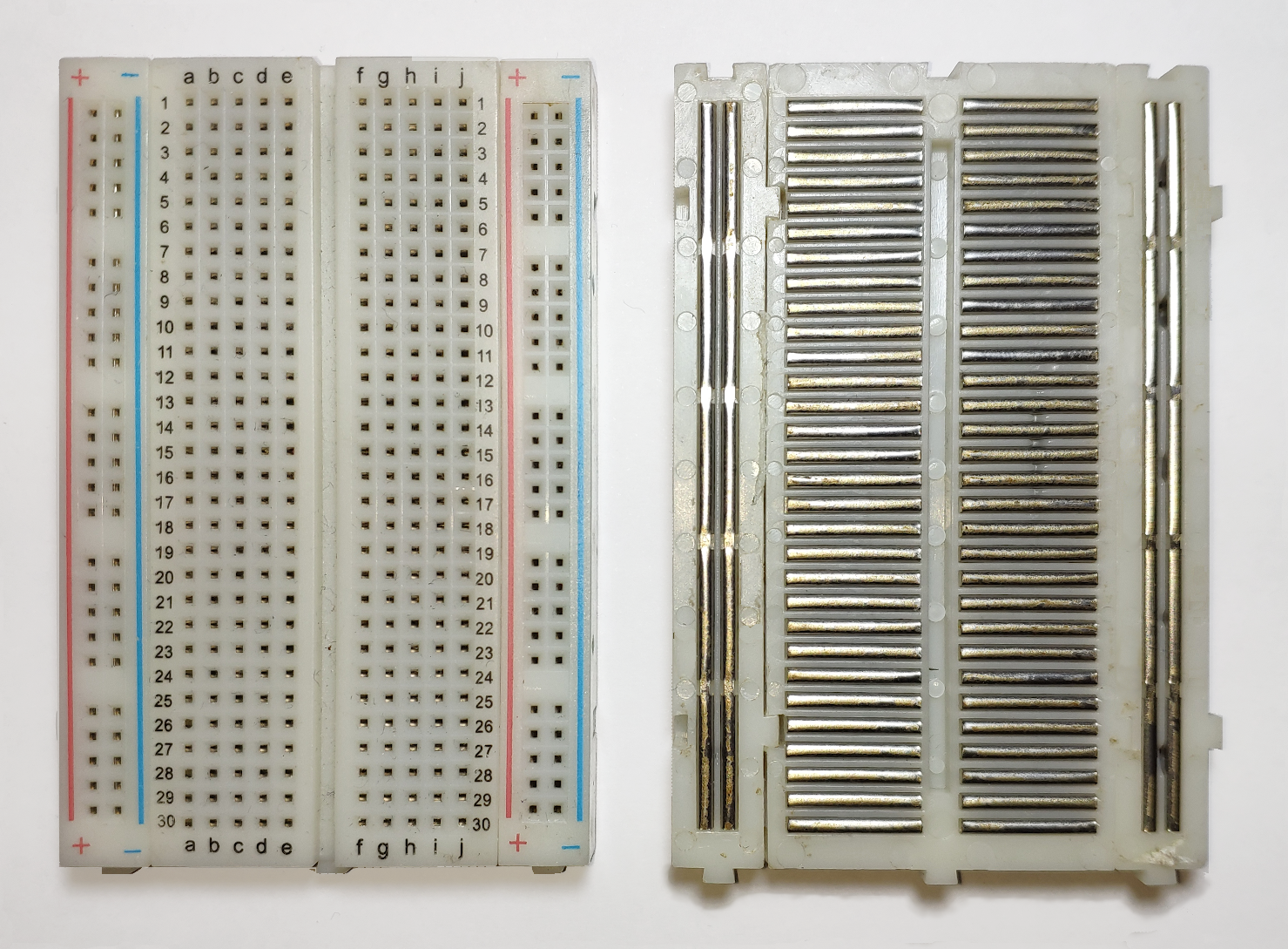
Left: top. Right: metal clips underneath. Short clips = rows of five. Long clips = power rails.
| Region | How the holes are tied |
|---|---|
| Terminal strips | Each numbered row of five (a–e or f–j) is one net. Same number across the trench is not joined |
| Power rails | Each + column is one long net. Each − column is another |
| Rail gaps | Many boards break each rail halfway. A short jumper across the gap joins the two halves |
Power rails are often split in the middle
A full-size board has a + / − pair on each long edge. Every one of those four columns is usually two halves — the top half is not joined to the bottom until you bridge the gap. Look for a break in the red/blue line halfway along the edge.
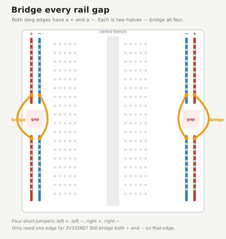
Four bridges if you use both edges: left +, left −, right +, right −. If you only use one edge for 3V3/GND, still bridge both + and − on that edge.
3. Pick the rails for this project
Choose one + rail and one − rail (same edge is simplest). Later steps put 3V3 on + and GND on −, then the ESP32-C3, VEML7700, LED, and display take power from those rails.
If your rails split in the middle, put a short jumper across each gap on the edge you use (+ to +, and − to −) so that edge is one continuous net end to end. Bridge the other edge too if you will use it. Skip this only if you have confirmed the rail metal is continuous.
Leave space for the ESP32-C3 across the centre trench and for the modules beside it so the jumpers stay readable.
Check
- You can point to your chosen
+and−rails - You know a pin in
a1does not connect tof1(trench in between) - Mid-rail gaps are bridged, or you confirmed your board has continuous rails
If it fails
| Symptom | Fix |
|---|---|
| Two parts share a row number but don't talk | They're on opposite sides of the trench. Jump across, or move both to the same side |
| Only half the rail has power later | Mid-rail gap. Bridge it with a short jumper |
Credit: empty board oomlout (CC BY-SA 2.0); connections photo Guhuru (CC0).


Checkpoint 1
- I can point to the
+rail and the−rail I'll use for 3V3 and GND - I know the left and right halves of a row are not connected
- Mid-rail gaps are bridged, or my rails are continuous
Stop here until every box is ticked.
Next: ESP32